"Piano" with RTOS
Intro
(Sorry for my appalling english)
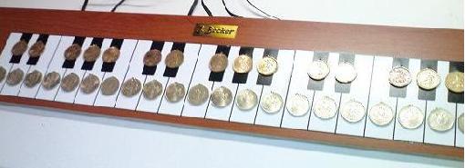
This arcticle describes a possibility of ADC usage to read touch sence buttons. As example we will encode program "Piano" for working with 36 capacitive sensing buttons (3 octaves). To avoid bore, we will make it polyphonic. For our project we will use demo-boards from PicKit2 kits based on PIC16F690, PIC16F886 or PIC16F887. In addition we use PIC16F88.
Here is two minutes demonstration video (sorry for my bad piano play).
HQ video (34 Mb)
LQ video (6.3 Mb)
Theory
Capacitive sensing
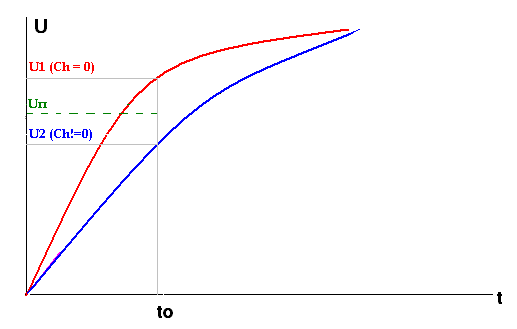
Capacitive sensing principles are described here. When we touch couper pad by finger, we increase scheme capacitance. The controller can detect capacitance increasing. In this case couper pad is used as capacitive sensor (like capacitor with small capacitance). If we will charge this capacitor with constant current, then voltage will increase in inverse proportion to capacity. Let's assume that we make measures of voltage on capacitor at the same times after start of charging. It is evident that low-capacity capacitor will have charged less than the capacitor of large capacity. Look at the picture:
Two capacitors C1 and C2 (capacitance of C1 is less then capacitance of C2) are charged with the same current. At the time t0 voltage at C1 increased by more than at C2. We know that touching couper pad by finger will increase capacitance. Imagine that we periodically charge/discharge capacitor (capacitive sensor) and makes measurings of voltage every time with same delay after start. While capacitance of sensor remain unchanged, we will read the same voltage's value. But when we will touch sensor by finger, the capacitance will increase and voltage will decrease. Thus we can detect the touching.
This principle of reading voltage on capacitive sensor after the same delay after start of charging we will use to read our touch buttons.
Implementation
We need four things:
- a capacitive sensor;
- a current source;
- a precise delay;
- a voltage meter.
First of all we need a capacitive sensor. We can use any metal plate, e.g. a coin.
Now we need a current source. Ideally, it must be a source of constant current. Is there any way to simplify this requirement? Can we apply just a RC-circuit? Look at the picture:
Capacitors C1 and C2 (C1 < C2) are in RC-circuit with the identical values of resistance. It is obviously that C1 will be charged faster than C2. The charge digrams are not linear, however we can determine in which case the capacitance is larger, because of at the time t0 values of voltages are different. Thus we can use simple RC-circuits instead of current sources.
Next we need to form a precise delay. Due to fact that time of charging is too little, we can form this delay with empty cycle. While delay is active we have to disable interrupts to avoid increasing time of charging.
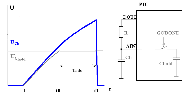
And we will use ADC module as a voltage meter. Look at the picture:
When we need to measure capacitance, we follow that steps:
- At the begin: U(Ch)=0, AIN is digital output = "0", DOUT = "0".
- At the point t pin DOUT becames "1", and pin AIN switches to analog input mode.
- At the point t0 we set GODONE = 1 to start AD convertion. Writing 1 to GODONE will disconnect internal capacitor Chold from external scheme and the voltage on Chold will be held and measured.
- After the measuring is done (at moment t1) pin AIN switches to digital output with "0"-state to discharge Ch.
- Pin DOUT set to "0" to reduce power consumption.
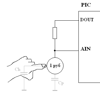
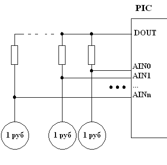
As a result we have a scheme to connect one touch button:
(In out example we use 1 ruble coin as capacitive sensor). While we do not touch a coin by finger, PIC measures the Cp - sum of capacitance of analog input pin, capacitance between coin and ground, coin and other coins, between wires. When we touch coin by finger, we add capacitor Ch (human), the resulting capacity increases.
Many buttons
We can to connect coins to all analog inputs of controller.
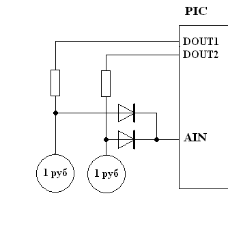
But thus we are limited by number of analog inputs (e.g. 7 at PIC16F88). Piano with 7 keys will be too uninteresting. We need more keys. Let's try to modify our scheme to get possibility of connection more than one button per one analog input. Do do it we just add a splitting diodes:
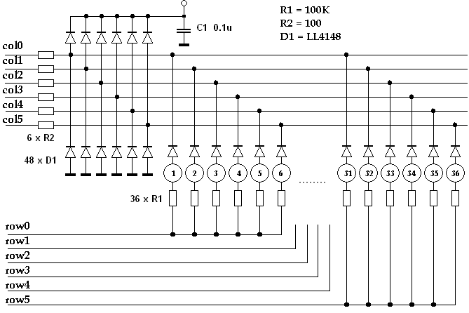
As you see at the picture, we can measure capacitance of each sensor separately using only one analog input by controlling digital outputs DOUT1 and DOUT2. Thus we can connect to one analog input three, four, five or more keys. We are limitted by number of pins that can be used as digital control pins DOUTx only.
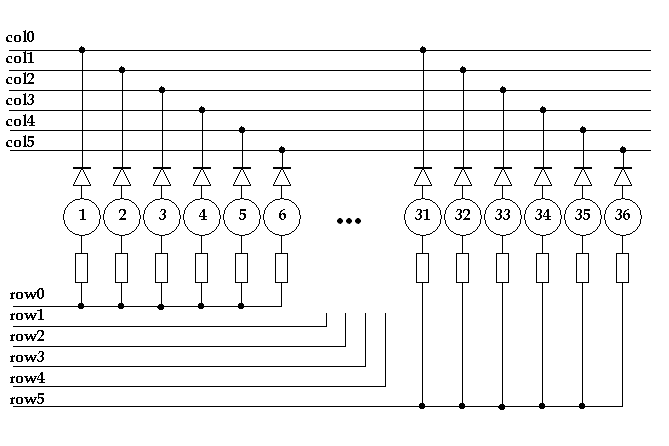
If we will use 6 analog inputs and 6 control digital outputs, then we can to read matrix of 6x6 = 36 capacitive sensors! As a result we have a scheme of touch buttons connecting:
That's it!
Notes
This method was successfully applied for work with 36-keys keyboard. But there are some disadvantages that should be prevented at the design stage.
Temperature drift
The capacitance of Chold and Cp and the resistance of R have the temperature drift. The speed of capacitive sensor charging will be different for different temperatures.
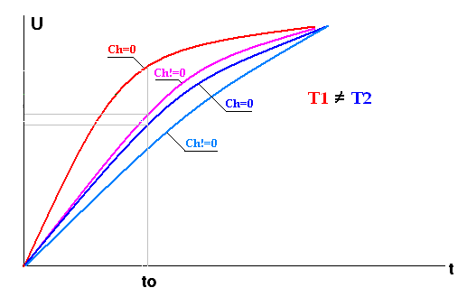
Here are diagrams of RC-circuit charging for touched and untouched buttons for very different temeratures. It is visibly that speed of touched sensor charging at T1 is same as speed of untouched sensor charging. So you should remember that treshold voltage sometimes must be recounted (at least 1 time per day).
Noise
Our finger is a source of noise for capacitive sensor. In reality in this case capacity charging diagram will look like this:
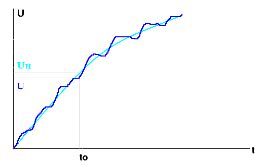
Ideal diagram shown in cyan. The ideal voltage at t0 will allways eq. to Uи. Real diagram shown in blue. Real voltage value will have some deviation within Uи. Depending on interference phase on moment of start of measuring U will be greater or less than Uи.
This noise will not inhibit when sensor touched by finger directly, because in this case we introduce significant additive capasitance in our scheme. But when sensor touched through some surface (e.g. glass or paper), the additive capacitance is relatively small. The speed of charge will change slightly. The presense of noise will complicate voltage drop detecting. In this case it may be nessesary to make measures several times at to take an average value for more accurate detection of button is pressed.
Analog input's capacitance
All controller's inputs have their own capacitance. This copacitance takes part in out measurments too. The problem is that all inputs have different capacitance, because they have different schematic solutions. This will cause different speeds of capasitor voltage rising on different pins. Thus our program should know that all input pins can have their own trigger tresholds.
Sound generation
Low frequency meander
Using meander of sound frequencies is the most common way to generate sound in embedded systems. For example to make 1KHz sound we generate 1 KHz square meander. In most applications that's enough: microwave ofen tell us that food is heated, refrigerator remind us that door is not closed, ect.
This way of sound generation is very simple and quite informative: we can generate sounds of different frequencies, durations, sequences, ect. Can we get polyphony with this method? Yes, we can. We can to generate 2 meanders on 2 controller's pins, or 3 meanders on 3 controller's pins, or 4 on 4, ect. And then we can mix them schematically. But this method have some disadvantages:
- is requires several pins to generate sound (8 pins for 8 channels);
- generation of two meanders is more difficult task than generation of one meander;
- sound generated by square wave is quite unpleasant.
Using DAC
PIC controllers have not internal DAC module, bat we can use PWM module with high frequency sampling (higher than we can hear). Using DAC (PWM) we can generate any type of signal: square, triangle, sinus, ect.
PWM generated signal is filtered by low-pass filter to suppress PWM frequency. So we have constant voltage level after filter while duty cycle will remain constant. When duty cycle get more longer, voltage level became greater. When duty cycle get shorter, voltage level becames less. It is obviously, that voltage level = 0 when duty cycle == 0; and voltage level = Vdd when duty cycle == max.
How to generate meander using PWM?
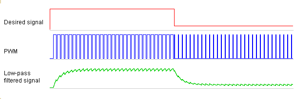
Look at the picture below:
When we need to generate "1"-state, we set duty cycle at maximum (PWM duty cycle on picture is not at maximum; this is for visibility: we see that PWM frequency more greater than meander frequency). When we need to generate "0"-state, we set duty cycle at minimum.
PWM signal bypasses through the low-pass filter, and we get meander (green diagram). In reality frequency of PWM is more greater than frequency of signal, therefore green diagram will look more likely meander.
How to generate 2-channel signal?
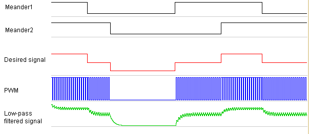
Now we need to generate signal, which is the sum of two meanders with different frequencies. In previous example we assumed that "1"-state of meander is a maximum when generated one-channel signal. Now we assume that maximum is "1"+"1" state. Look at the picture:
We set PWM duty cycle at maximum only when both signals are at "1"-state. When only one signal in "1" state and other in "0"-state, we set PWM duty cycle at middle (50%). Green diagram shows the signal after low-pass filter.
Now, when we know how to generate sum of 2 meanders, we can generate the sum of 3, 4, 5, ect. meanders.
How to generate sinus?
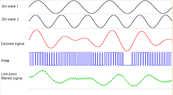
In fact, generating of sinus is the same as generating sum of meanders. We take samples at regular intervals and set PWM duty cycle according current value. For example, duty cycle will be set at maximum when we take a sample at the phase 90%; duty cycle will be set at 50% when we take a sample at the phase 0% or 180%; duty cycle will be set at 3/4 then we take a sample at the phase 30%.
Now we can generate a sum of two sinuses:
three sisuses, five sinuses, two sinuses and three meanders, ect.
Development
So, we need to encode program "Piano" that:
- reads states of 36 touch buttons (keys);
- generates eight-channels sound.
In addition we will add a possibility to change musical instrument by pressing a button.
We will generate sound using internal PWM module that configured at maximum possible frequency at 8-bit resolution. We use Fosc = 20MHz, therefore PWM frequency is 78 KHz. Sound sampling rate we will set as 1/4 of PWM frequency = 19.5 KHz (we can't set sampling rate higher because of 8-channel signal generating takes long time).
Tasks
First of all we split program by tasks. What tasks controller solves?
- Keyboard scanning: snans 36 touch buttons (keys);
- Sound generation: forms PWM duty cycles according to pressed keys and selected musical instrument;
- Button polling: waits for button pressed and select next musical instrument.
The generation of sound is a time-critical task. Saund sample rate is 19.5 KHz, therefore we must make all mathematical operations of mixing eight channels in 50 us (250 precossor's cycles). (In fact less than 50 us, because controller has to be able to do other tasks.) It is reasonable to split this task:
- first will mix eight channel sound and form PWM duty cycle (it should be performed faster than 50 us). This task will be placed incide interrupt service routine;
- second will form sound parameters for first task according to pressed keys (it will work in background mode).
Keyboard scanning and button polling are not time-critical tasks. Thus, we get three RTOS-tasks: "Keyboard", "Button" and "Sound parameters maker"; and one non-RTOS task: "Synthesizer" - it will be placed inside ISR.
"Keyboard"
This task will scan all 36 touch buttons and form array of keys state. Besides it will inform other tasks about changing keyboard state (some keys were pressed and/or some keys were released).
"Button"
This task will poll button state with debounce. This task will change musical instrument when button will be pressed.
"Sound parameters maker"
This task will wait message from task "Keyboard" thet keyboard state was changed. After receiving this message the task will form sound variables that tell to "Synthesizer" which channel plays sound (and parameters of sound: key number and frequency), and which channel is silent.
"Synthesiser"
To synthesize the sound we will create an 64-points array, that contains digitized period of sinus. To generate sound synthesizer on each execution (1 time per 51.2 us) gets next point from this array (the step depends of current channel's frequency: higher frequency makes large step value, lower frequency makes short step value) and forms PWM duty cycle.
When sinthesizer needs to play two channels, it takes two values from sinus array (each of them depends of channel frequency and current signal phase). The sum of these values is a new PWM duty cycle value. Three, four, ect. channel sound is formed in the same way.
We will use four arrays to make possible use one of four musical instruments.
Data
Here we give answer to two questions:
- What data our program will operate?
- How data will be exchanged between tasks?
For keyboard
Here we need some array to store current keys state. Our piano has 36 keys, therefore we need at least five bytes array. Further, we need some variable to address any single bit in array. Simplest way is to use two variables of type char. One of them will indicate byte position in array, and another will represent mask of bit in byte.
Besides, as said above, each analog input have it's own trigger treshold. Therefore we need an array to store tresholds for each analog input. We need array of six bytes as we have 6 analog input.
Let's create a structure to hold all these data:
struct
{
    unsigned char   Data[KBD_SIZE];         // Array of bits: =1 - key pressed
    unsigned char   cDataPos;               // Two variables to point current
    unsigned char   cDataMask;              // bit while keyboard scanning.
    unsigned char   Porogs[KBD_COLUMNS];    // Array of reference values of
                                            // ADC to determinate that key is
                                            // pressed
} KBD;
Note that we use constants KBD_SIZE (=6) and KBD_COLUMNS (=6) to make the possibility to increase or reduce the number of keys with minimum code modifications.
Although I used PIC16F88, we need to take into consideration that other controllers may be used. Different controllers have different pins that can work as anlog inputs. Therefore we have to define data structure that allow us to assign different pins to be analog inputs or digital outputs. Let's assume that keyboard have a form of matrix. Digital control outputs are in rows, and analog inputs are in columns. To describe digital output we need two variables: address of port register and position of bit in port. The analog input discription is a bit more complex, and here we need four variables: analog channel, address of port register, addres of tris register and position of bit in port. Thus we have two structures to describe pins:
typedef struct          // Type for analog input (see array COLUMNS below)
{                       //
    char  cADCChannel;  // Analog channel
    char *pPort;        // Pointer to PORT register
    char *pTris;        // Pointer to TRIS register
    char  cMask;        // Bit mask for PORT and TRIS
} TColumn;

typedef struct          // Type for digital control output (see array ROWS below)
{                       //
    char *pPort;        // Pointer to PORT register
    char  cMask;        // Bit mask for PORT
} TRow;
Now, using these two types we can create two arrays to assign pins as digital outputs or analof inputs.
For synthesizer
To simulate different musical instruments we need four arrays, each of which will contain digitized period of signal with different freauency characteristics (see file sinus.c). To increase speed of accessing to elements of array it is reasonable to copy current instrument (sample) into RAM. So we reserve 64 bytes in RAM to make image of current sample from ROM:
char Sample[64];
Besides we need a variable hat indicate current sample. The choice of sample is made by task "Button", and it is reasonable to make this variable static for this task:
static char s_cCurSample;
And last, synthesizer should know which channel plays which note (frequency and current phase of signal). Thus we have a structure:
typedef struct          // Type for sound control variables
{
    unsigned int F;     // Frequency
    unsigned int f;     // Phase
    unsigned char key;  // Played key
} TSound;
Encoding
"Button"
Sample should be changed when user presses a button. But we should remember that user may never press a button, therefore it is nessesary to initialize array in RAM before waiting the button pressing.
void Task_Button (void)
{
    static char s_cCurSample;   // Current sample

    s_cCurSample = 0;

    CopySample(s_cCurSample);
    for (;;)
    {
        //------------------------------------------------------------------------------
        //  Wait for key press (with debounce)
        //------------------------------------------------------------------------------

        do
        {
            OS_Cond_Wait(!pin_BUTTON);
            OS_Delay(40 ms);
        } while (pin_BUTTON);

        //------------------------------------------------------------------------------
        //  Chenging sample, copy sample info into RAM
        //------------------------------------------------------------------------------

        s_cCurSample++;
        if (s_cCurSample >= MAX_SAMPLES) s_cCurSample = 0;
        CopySample(s_cCurSample);

        //------------------------------------------------------------------------------
        //  Wait for key release
        //------------------------------------------------------------------------------

        do
        {
            OS_Cond_Wait(pin_BUTTON);
            OS_Delay(40 ms);
        } while (!pin_BUTTON);


    }
}
Note that variable s_cCurSample defined as static, as it is important to keep it's value after task switching. Function CopySample just copies array from ROM into RAM:
void CopySample (char c)
{
    char n;
    c &= 3;
    for (n = 0; n < 64; n++) Sample[n] = SAMPLES[c][n];
}
"Keyboard"
Ths task every 10 ms scans all 6 rows of keyboard matrix. In the begin of task all treshold values are zeroed. Function that reads keys in row checks these values for zero and writes to them measured ADC data minus 15% (=85%).
Note. If you will use surface between finger and sensor, then treshold voltage should be about 95% of untouched sensor.
void Task_Keyboard (void)
{
    static char n;
    static char s_cChanged;

    //------------------------------------------------------------------------------
    //  Make call of ReadRow to make sure that all analog input pins are
    //  configured as digital output (to discharge capasitors)
    //------------------------------------------------------------------------------

    ReadRow(0);

    //------------------------------------------------------------------------------
    //  First time all reference values are cleared (not set)
    //------------------------------------------------------------------------------

    for (n = 0; n < KBD_COLUMNS; n++) KBD.Tresholds[n] = 0;

    for (;;)
    {
        //------------------------------------------------------------------------------
        //  Set bit mask for first key
        //------------------------------------------------------------------------------

        KBD.cDataPos  = 0;                  // Byte number
        KBD.cDataMask = 0x01;               // Bit mask in byte
        s_cChanged = 0;                     // Boolean value: =1 - keys states
                                            // were changed

        for (n = 0; n < KBD_ROWS; n++)      // Loop by all rows
        {
            s_cChanged |= ReadRow(n);       // Measuring of all sensors (key) in a
                                            // row may take about 500 us. So
                                            // between row measures we switch
                                            // tasks.
            OS_Yield();
        }

        //------------------------------------------------------------------------------
        //  If keyboard state was changed, then send a message to Task_Sound
        //------------------------------------------------------------------------------

        if (s_cChanged)
        {
            OS_Msg_Send_Now(msg_KBD, (OST_MSG) KBD.Data);
        }

        OS_Delay(10 ms);
    }
}
Now we will encode function that reads capacitive sensors.
char ReadRow (char row)
{
    //------------------------------------------------------------------------------

    char        m, a, i, k;             // Additional variables
    char        col;                    // Current analog input (column)
    TColumn     Column;                 // Use a variable to redice code size and
                                        // increaze speed.

    static char s_Changes[KBD_SIZE];    // For debounce: changes since last reading

    static bit  s_bChanged;             // ariable o be returned

    //------------------------------------------------------------------------------

    *ROWS[row].pPort |= ROWS[row].cMask;// Set row control output to "1"

    s_bChanged = 0;                     // First we suppose that there were not
                                        // any changes in keyboard state

    //******************************************************************************
    //   Loop for all columns
    //******************************************************************************

    for (col = 0; col  < KBD_COLUMNS; col++)
    {
        //------------------------------------------------------------------------------
        // Copy channel info into RAM variable to reduce code size
        //------------------------------------------------------------------------------

        Column.pPort       = COLUMNS[col].pPort;
        Column.pTris       = COLUMNS[col].pTris;
        Column.cMask       = COLUMNS[col].cMask;
        Column.cADCChannel = COLUMNS[col].cADCChannel;

        //------------------------------------------------------------------------------
        //  Select ADC channel
        //------------------------------------------------------------------------------

        CHS0 = 0;
        CHS1 = 0;
        CHS2 = 0;
        if (Column.cADCChannel & 0x01) CHS0 = 1;
        if (Column.cADCChannel & 0x02) CHS1 = 1;
        if (Column.cADCChannel & 0x04) CHS2 = 1;

        #if defined(_16F887) || defined(_16F886) || defined(_16F690)
        CHS3 = 0;
        if (Column.cADCChannel & 0x08) CHS3 = 1;
        #endif

        //------------------------------------------------------------------------------
        //  Start measuring
        //------------------------------------------------------------------------------

        GIE = 0;                        // Disabling interrupts while making delay
                                        // to charge capasitor

        *Column.pTris |=  Column.cMask; // Start capasitor sensor charging by
                                        // set analog pin for input (high imp.)

        for (m = 0; m < 3; m++) NOP();  // CHARGING DELAY

        GODONE = 1;                     // Start AD conversion.
        GIE = 1;                        // Now we can enable interrupts

        while (GODONE) continue;

        //------------------------------------------------------------------------------
        //  AD conversion is done. Now forming key states array.
        //------------------------------------------------------------------------------

        *Column.pTris &= ~Column.cMask;
        *Column.pPort &= ~Column.cMask; // Discharge capasitor by switching analog
                                        // input to output "0"
        a = ADRESH;

        //------------------------------------------------------------------------------
        //  Set reference for current channel if it not set yet
        //------------------------------------------------------------------------------

        m = KBD.Tresholds[col];         // Copy element of array in vaiable to
                                        // reduce code size
        i = 0;
        if (a < m) i = KBD.cDataMask;   // Compare with reference value. If just read
                                        // value is less than reference, then
                                        // capasitor were charged to slow. It
                                        // means that key is pressed.

        if (!m)                         // If reference is not set (is zero) then
        {                               // set it as 88% of current ADRESH value
            m = a >> 3;
            KBD.Tresholds[col] = a - m;
        }

        //------------------------------------------------------------------------------
        //  Setting new keyboard state (with debounce)
        //------------------------------------------------------------------------------

        m  =  KBD.Data[KBD.cDataPos];   // To reduce code size we will work with
        k  =  s_Changes[KBD.cDataPos];  // copy of array's element

        //------------------------------------------------------------------------------
        if ((m ^ i) & KBD.cDataMask)
        {                               // Key state was changed:
            if (!(k & KBD.cDataMask))   //   Just now:
                k |=  KBD.cDataMask;    //     Set change token

            else                        //   Not just now:
            {
                m ^=  KBD.cDataMask;    //     Set new key state
                s_bChanged = 1;         //     Form variableto be returned
                k &= ~KBD.cDataMask;    //     Reset change token
            }
        //------------------------------------------------------------------------------
        } else {                        // Key state remain unchanged
            k &= ~KBD.cDataMask;        //   Reset change token
        }
        //------------------------------------------------------------------------------

        KBD.Data[KBD.cDataPos] = m;     // Restore array's elements from
        s_Changes[KBD.cDataPos] = k;    // temp variables

        //------------------------------------------------------------------------------
        //   Set bit mask for next key
        //------------------------------------------------------------------------------

        KBD.cDataMask <<= 1;
        if (!KBD.cDataMask)
        {
            KBD.cDataMask = 0x01;
            KBD.cDataPos++;
        }

    };

    *ROWS[row].pPort &= ~ROWS[row].cMask;   // Set row control output to "0"

    return s_bChanged;

}
Let's pay attention on forming delay string:
for (m = 0; m < 3; m++) NOP();
In this case program forms pause for resistance 100K in RC-curcuit. This delay provides capasitive charge up to Vdd/2. If you suppose to use other values of resustors, it will be better (but not nessesary) to recount constant in for-cycle. E.g. for 200K this cycle should be executed 6 times.
"Sound"
This task will accept message from Task_Keyboard and form sound variables for syntheszer. After accepting a message, it will be copyed into internal array. Then we check all sound variables to:
- stop sound for no longer pressed keys;
- delete already played keys from list of keys (internal array);
- count number of free channels.
After that operation we have a variable cFreeSounds that shows how many channels are free, and list of just pressed keys. If this list is not empty and there are some free channels, than new sounds will be added.
TSound      S[MAX_CHANNELS];    // Sound variables

void Task_Sound (void)
{
    OST_MSG         msg;            // Variable to receive message
    unsigned char   Data[KBD_SIZE]; // Array where keyboard state will be copied to
    unsigned char   cMask;          // Two temparary variables to address bits in
    unsigned char   cPos;           // array.

    unsigned char   cFreeSounds;    // How many free channels we have.
    unsigned char   i, j;           // Temp variables

    //------------------------------------------------------------------------------

    for (;;)
    {
        //------------------------------------------------------------------------------
        //   Wait for changing of keybaord state. Copy keyboard state into Data
        //   array
        //------------------------------------------------------------------------------

        OS_Msg_Wait(msg_KBD, msg);

        for (i = 0; i < KBD_SIZE; i++) Data[i] = ((char*)msg)[i];

        //------------------------------------------------------------------------------
        //  If key is played now, then it will be deleted from list of pressed
        //  keys. At the same time we will count number of free sound channels.
        //------------------------------------------------------------------------------

        cFreeSounds = 0;

        for (i = 0; i < MAX_CHANNELS; i++)      // Check all channels
        {
            if (S[i].key == 0)                  // If current channel is quiet then
            {                                   // increase number of free channels.
                cFreeSounds++;
                continue;
            }

            j = S[i].key - 1;                   // Forming bit address according to
            cMask = 1 << (j & 7);               // current sound channel
            cPos = j >> 3;

            if (Data[cPos] & cMask)             // If key is still pressed then delete it
                Data[cPos] &= ~cMask;           // from list of pressed keys
            else
            {
                cFreeSounds++;                  // Else stop channel's sound and increase
                S[i].key = 0;                   // free channels counter
            }
        }

        //------------------------------------------------------------------------------
        //  Now variable cFreeSounds contain number of free channels. They can be
        //  used to play sounds for just pressed keys.
        //------------------------------------------------------------------------------

        cMask = 0x01;   // Start searching just pressed keys
        cPos = 0;
        j = 0;          // Keys counter
        i = 0;          // Channels counter

        while ((j < KBD_KEYS) && cFreeSounds)
        {
            if (Data[cPos] & cMask)     // Is key pressed?
            {                           // Yes.
                while (S[i].key) i++;   // Search for free channel

                                        // Forming sound control variable:
                S[i].F = Freq[j];       //      Frequency
                S[i].f = 0;             //      Phase
                S[i].key = j + 1;       //      Store current key
                cFreeSounds--;          //      Decrease number of free channels
            }

            j++;                        // Get next key
            cMask <<= 1;
            if (!cMask)
            {
                cMask = 0x01;
                cPos++;
            }
        }
    }   //  for(;;)
}
Synthesizer
As we decided before, code for sound generation will be placed into ISR. We use interrupt on TMR2. TMR2 is already used by PWM module (PWM frequency is 78KHz). We need for interrupt occured with frequency 19.5 KHz. Therefore postscaler for TMR2 will be set to 4.
So, interrupt on TMR2 occures every 51.2 us. Here we will generate a sound (or PWM duty cycle).
void interrupt isr (void)
{
    static  unsigned    char    prs;        // OS_Timer's prescalser
            signed      int     temp_dac;   // Summa of all signals
            unsigned    char    m_cDAC;     // Value of DAC


    TMR2IF = 0;
    temp_dac = 0;

    //------------------------------------------------------------------------------
    //  Forming DAC value
    //------------------------------------------------------------------------------

    SOUND(0);
    SOUND(1);
    SOUND(2);
    SOUND(3);
    SOUND(4);
    SOUND(5);
    SOUND(6);
    SOUND(7);

    temp_dac >>= 3;     // Divide by number of channels (8)

    m_cDAC  = *((char*)&temp_dac+0) + 0x80;
    m_cDAC >>= 2;

    //------------------------------------------------------------------------------
    //  Out currect DAC value through PWM
    //------------------------------------------------------------------------------

    CCP_bit1 = 0;
    CCP_bit0 = 0;
    if (temp_dac & 2) CCP_bit1 = 1;
    if (temp_dac & 1) CCP_bit0 = 1 ;
    CCPR1L = m_cDAC;

}
Macro SOUND is:
#define SOUND(x)                                        \
    if (S[x].key) {                                     \
        temp_dac += Sample[*((char*)&S[x].f+1) & 0x3F]; \
        *((char*)&S[x].f+1) += *((char*)&S[x].F+1);     \
        *((char*)&S[x].f+0) += *((char*)&S[x].F+0);     \
        if (CARRY) *((char*)&S[x].f+1) += 1;            \
    }
It used for conveniens. After checking for channel activity (field cKey != 0) we read next value from an array of sample data (according to sound frequency F and current phase f) and add it to common sum temp_adc. After that we recount phase of sound.
Now, we just need to add work with system timer. Our system tick will be 10 ms (every 200th interrupt):
    //------------------------------------------------------------------------------
    //  Call system timer once per 200 periods (interval = 10 ms)
    //------------------------------------------------------------------------------

    if (!--prs)
    {
        OS_Timer();     // System timer
        prs = 200;
    }
main()
Here we will initialize PIC periphery and operating system, create tasks and run shceduler. All tasks will have identical priority (0 - highest).
void main (void)
{
    //------------------------------------------------------------------------------
    //  Init PIC periphery
    //------------------------------------------------------------------------------

    Init();

    //------------------------------------------------------------------------------
    //  OSA initialisation
    //------------------------------------------------------------------------------

    OS_Init();

    //------------------------------------------------------------------------------
    //  Create all task with identical priority
    //------------------------------------------------------------------------------

    OS_Task_Create(0, Task_Sound);
    OS_Task_Create(0, Task_Button);
    OS_Task_Create(0, Task_Keyboard);

    //------------------------------------------------------------------------------
    //  Enable interrupts and run system
    //------------------------------------------------------------------------------

    OS_EI();
    OS_Run();
}
OSA configuration
To configure our project we will use OSAcfg_Tool wizard. Run OSAcfg_Tool.exe and follow steps below:
1. Select project folder
Press button Browse in top-right corner of dialog window. Select folder where project located in ("C:\TEST\PICKIT2\PIANO"). Press "OK". If config file OSAcfg.h does not exist yet, then program will ask you "do you want to create this file?". Answer "Yes".
2. Set project name
In field Name you can enter the name for your project. It is not nessesary. Name is used to avoid confusing in future. Enter name "SENSOR PIANO".
3. Select platform
This item is not nessesary too. It allows to view in real time how march RAM OSA needs with current configuration. Select platform: 14-bit (PIC12, PIC16)(ht-picc). Now, on any configuration change, program will show us number of used bytes in each RAM-bank in RAM statistic sector.
4. Configure project
All tasks have identical priority. Therefore we can check Disable priority. This will reduce code size and increase scheduler's speed.
Next step is setting number of tasks that will be active at same time. Three in our case.
Our program uses many variables. Thus it is reasonable to allocate all system variabls in higher RAM-bank. Select bank2 in combo OSA variables bank.
Now we tell to system that we need task timers (as we use OS_Delay in our porgram). Check Task timers. Due to we do not use delays longer than 256 system ticks (2.5 sec), it is recommended to set task timer type to char. It will increase speed of OS_Timer work.
And last: check Use in-line OS_Timer() to increase speed of OS_Timer() execution.
5. Save and exit
Press Save button to save edited configuration file. Than press "Exit" to exit program. Now you can look into created file OSAcfg.h:
/******************************************************************************/
//
// This file was generated by OSAcfg_Tool utility.
// Do not modify it to prevent data loss on next editing.
//
// PROJECT NAME: SENSOR PIANO
// PLATFORM:     HT-PICC 14-bit
//
/******************************************************************************/


#ifndef _OSACFG_H
#define _OSACFG_H

//------------------------------------------------------------------------------
// SYSTEM
//------------------------------------------------------------------------------

#define OS_TASKS               3  // Number of tasks that can be active at one time
#define OS_DISABLE_PRIORITY       //

//------------------------------------------------------------------------------
// ENABLE CONSTANTS
//------------------------------------------------------------------------------

#define OS_ENABLE_TTIMERS          // Enable task timers
#define OS_USE_INLINE_TIMER        // Make OS_Timer service as in-line function

//------------------------------------------------------------------------------
// BANKS
//------------------------------------------------------------------------------

#define OS_BANK_OS             2  // RAM bank to allocate all system variables

//------------------------------------------------------------------------------
// TYPES
//------------------------------------------------------------------------------

#define OS_TTIMER_SIZE         1

#endif
Programming
Building a project
To build uor project we need next:
- Installed MPLAB IDE;
- Installed HI-TECH PICC STD compiler (PRO version will not work).
Now:
- Download RTOS OSA files and unpack it into "c:" (folder C:\OSA will be created);
- Unpack piano_en.rar into "C:\TEST\PICKIT2" (folder "PIANO" will be created);
- Open project for your controller with MPLAB IDE (there are four projects for controllers: 16F88, 16F690, 16F886, 16F887).
Note: if you want to install project into folder other then "C:\TEST\PICKIT2\PIANO", then you need to change include path to it through Project\Build options…\Project menu in Directories tab.
Build your project with Ctrl+F10.
Programming with PicKit2
Here you should to do next:
- connect programmer;
- select "PicKit2" through "Programmer\Select programmer" menu;
- select <3-State on <Release from Reset> in "Programmer→Settings";
- start programming "Programmer\Program";
- make "Programmer\Release from reset".
That's it!
Schematic
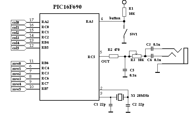
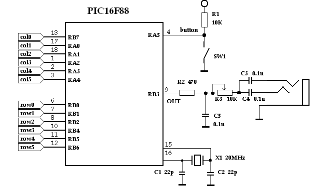
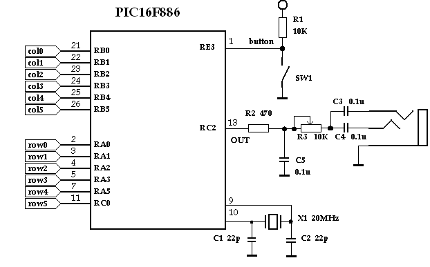
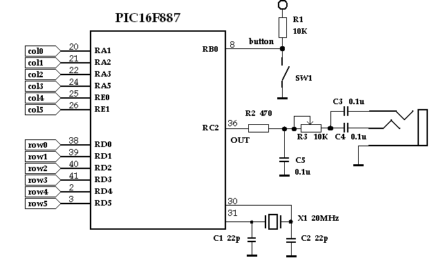
Here I'll describe pin scheme to connect keyboard matrix to different PICs: 16F690, 16F88, 16F886, 16F887.
Important notice: pins where columns will be connected to should no contain any external components except keyboard matrix. Elsewere these components will add their capasitance and resistance into scheme.
Analog inputs have additive ESD protection according to Microchip's document:Layout and Physical Design Guidelines for Capacitive Sensing (PDF).
Summary
So, this article described two interesting things for beginners:
- keys reading. Not usual keys, but touch keys. They can work in damp and in dust;
- sound generation (not usual beep, but polyphonic sound).
And I am sure that you will use these techniques in you projects in future to make your devices more interesting and life.
Why we used RTOS?
- RTOS provided us with multi-tasking. And we even didn't think about how to run all our tasks at the same time;
- We were able to break our program into simple tasks. Any of these tasks my be modified as you wish very easy;
- All our tasks are independed. This allows to use them in other applications.
What can we do now? Our program turned out to be quite flexible in adjusting:
- Do you wish to connect keyboard to other pins? Correct ROWS and COLUMNS arrays in file const.h and enjoy;
- Do you want more keys in keyboard? Redefine KBD_ROWS and KBD_COLUMNS constants and add new pins into ROWS and COLUMNS arrays;
- Do you want more channels? Increase MAX_CHANNELS constant and decrease sampling rate;
- Do you want more musical instruments? Add data into SAMPLES array in file sinus.c.
- ect.
You are limitted by your imagination only!
Good luck!
Victor Timofeev, 2009, april
osa@pic24.ru
