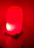
OSA : example for PIC10
Project
This example demonstrates using RTOS OSA under 12-bit microcontroller. Unrar file 3leds.rar into folder "C:\TEST\3LEDS". This programm written under PIC10F222 (you can rebuild it under F202 or 206).
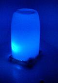
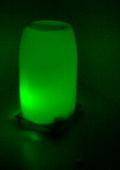
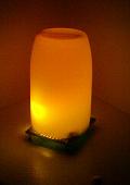
This program forms PWM signals to drive 7-color LED. It slowly changes width of pulses for every LED. There are four speeds of color changing.
Scheme
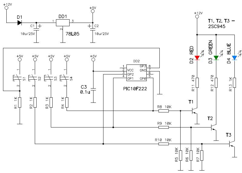
Here is scheme of device. Controller drives three n-p-n transistors. Every transistor controls LED. Notice that buttons and transistors are connected to same pins.
Button S1 makes red LED active.
Button S2 makes green LED active.
Button S3 makes blue LED active.
Button S4 canges work speed.
Note. Values of resistors R11, R12 and R13 are selected according to used LEDs.
Work description
Program contains three tasks:
- Task_Leds - forming pulses to drive LEDs.
- Task_Work - forming values of length for each LED.
- Task_Buttons - sans buttons.
Task_Leds
This task waits for TMR0 overflow. When overflow occures, all active LEDs are switchs on. Then task waits for TMR0 becames greater than intensity value of each LED and switch corresponding LED off. Program has three variables holding intensity values for each LED. When all LEDs becames switched off, other tasks can get control.
Two other tasks (Task_Work and Task_Button) waits for setting bits bRunTaskWork and bRunTaskButtons respectively. This bits are set by Task_Leds after all LEDs switchs off.
Task_Work
When task gets control, it checks is it time to change intenesity variables. There is a variable Speed. It's value changes every time when task get control. Speed of increasing (speed of intensity changing) are set by two MSB bits of variable Speed (Speed.cSpeed). When 5 lowes bits of variable Speed (Speed.cPrs) overflows, bit Speed.bTimeout becames set and function ChangeIntensity() called. This functions changes intensity values of all LEDs (variables Red, Green and Blue).
Task_Button
This task gets control one time in every 16 milliseconds, when bit bRunTaskButtons becames set. First all pins set as inputs. Then program checks state of pins: if any pin eq. to "0", then corresponding button is pressed. Buttons SW1, SW2 and SW3 set intensity of red, green or blue at maximum, respectively (two other LEDs will be switched off). Button SW4 increases value of Speed.cSpeed by 1. After all buttons checked, task waits for button release. Before exit from task, all pins set as output.
